Building on Mars
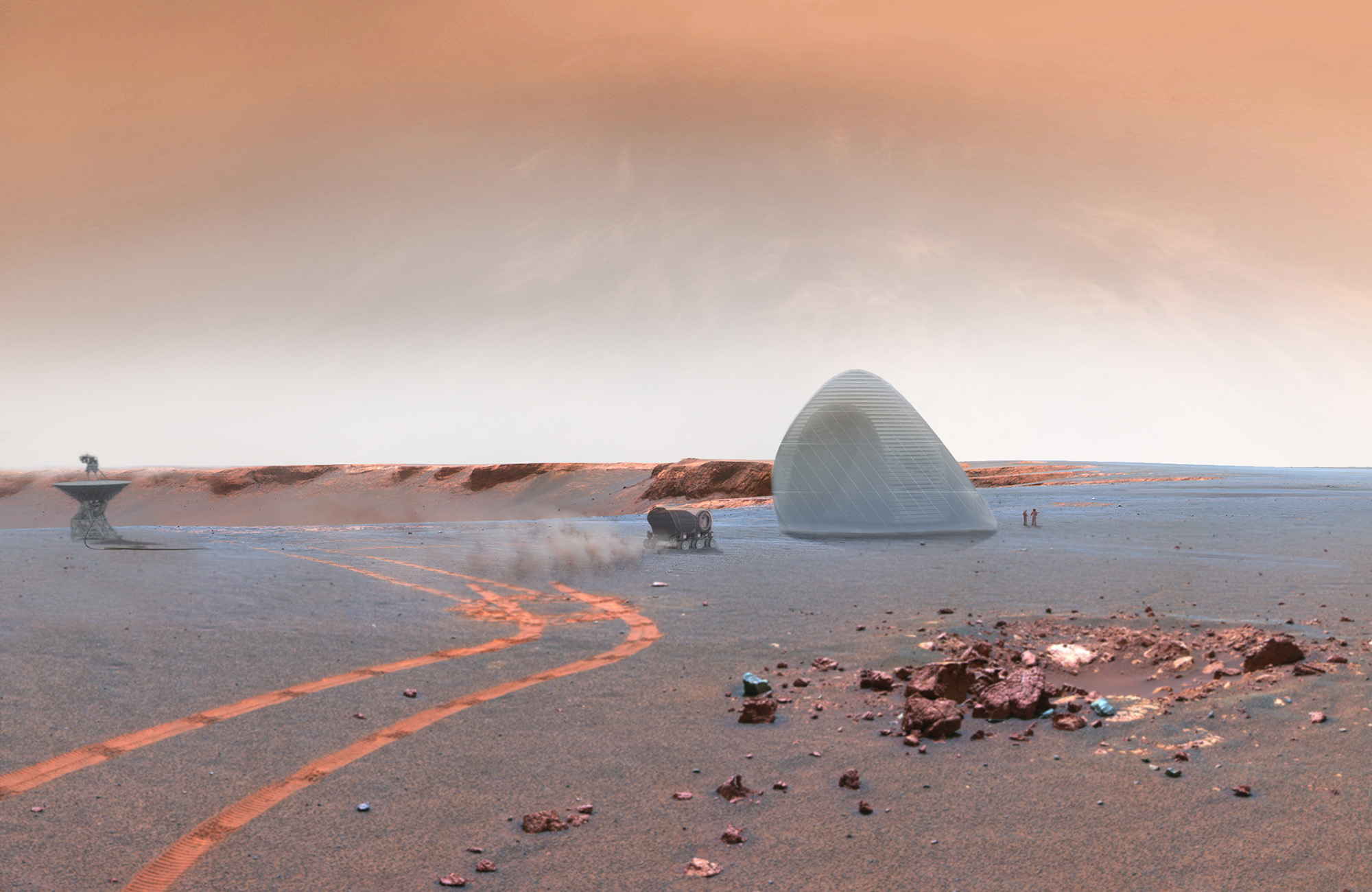
The potential of 3D Printing with in-situ materials on Mars is significant in that we may be able to build structures without bringing heavy equipment, supplies, materials, and structures from Earth. The ability of construction to be handled semi-autonomously before the arrival of astronauts with digital manufacturing techniques is as compelling as it is technically challenging. Because construction techniques and transit vehicles are so linked with the overall outcome of the habitat, Mars Ice House has outlined a deployment and construction sequence involving the use of a projected mars descent vehicle, a deployable membrane, and semi-autonomous robotic printers to both gather and deposit subsurface water ice.
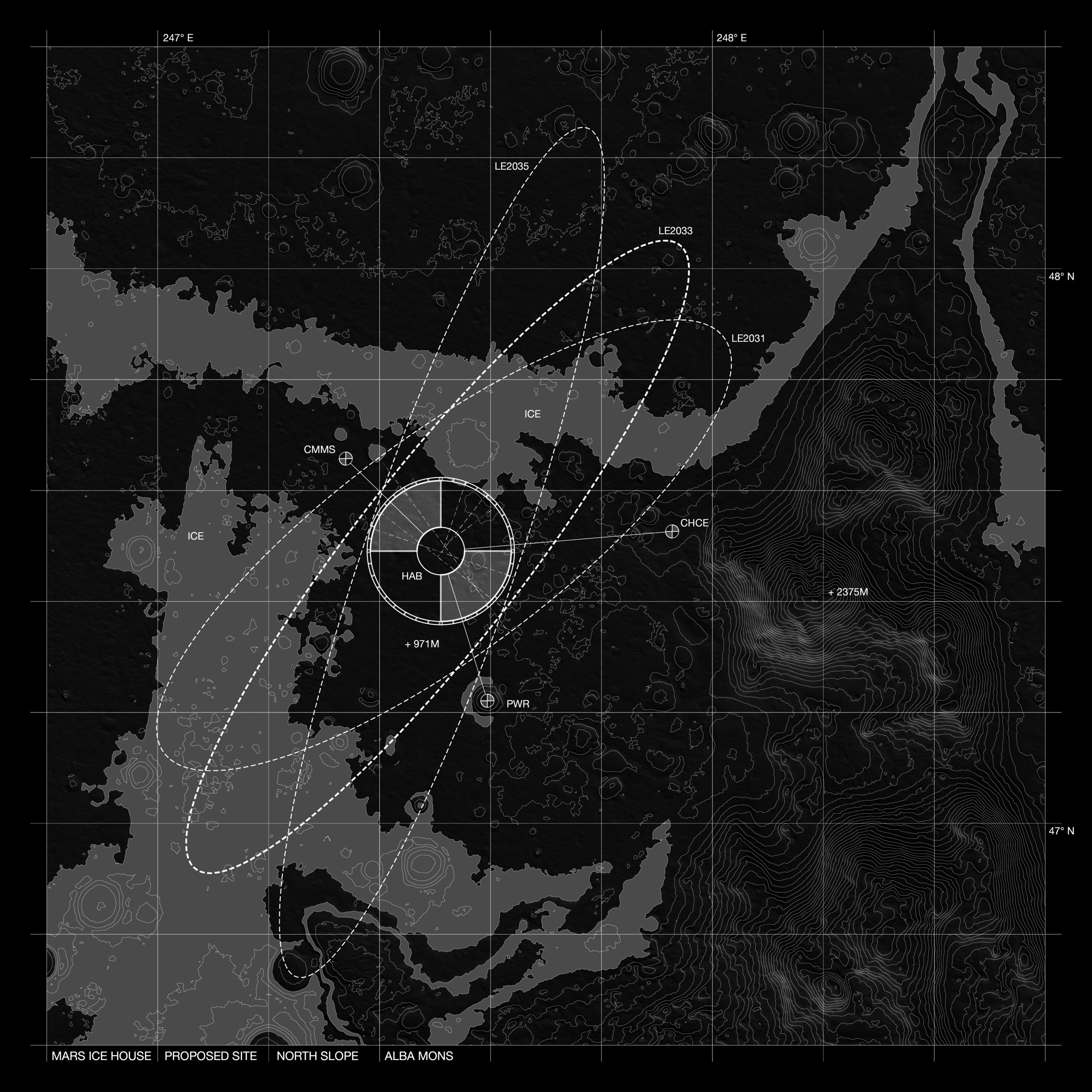
Site Selection
On Mars, water is abundant in the higher and lower latitudes. Site selection was determined by a multitude of parameters, which included the need to balance access to a shallow ice table from the surface (within 20cm-1m), with temperatures that remain below freezing throughout the Martian year. Considering requisites such as relatively gentle slopes and soft terrain for construction, as well as the desire for maximum possible solar exposure, we have selected an area on the northern flanks of Alba Mons between 45 N-50N latitude and 230 E – 270 E longitude. The volcano display flanks slopes of 2.5-5, allowing us to take advantage of the colder temperatures within the polar regions, while remaining as far south as the predicted distribution of ice permits for solar exposure.
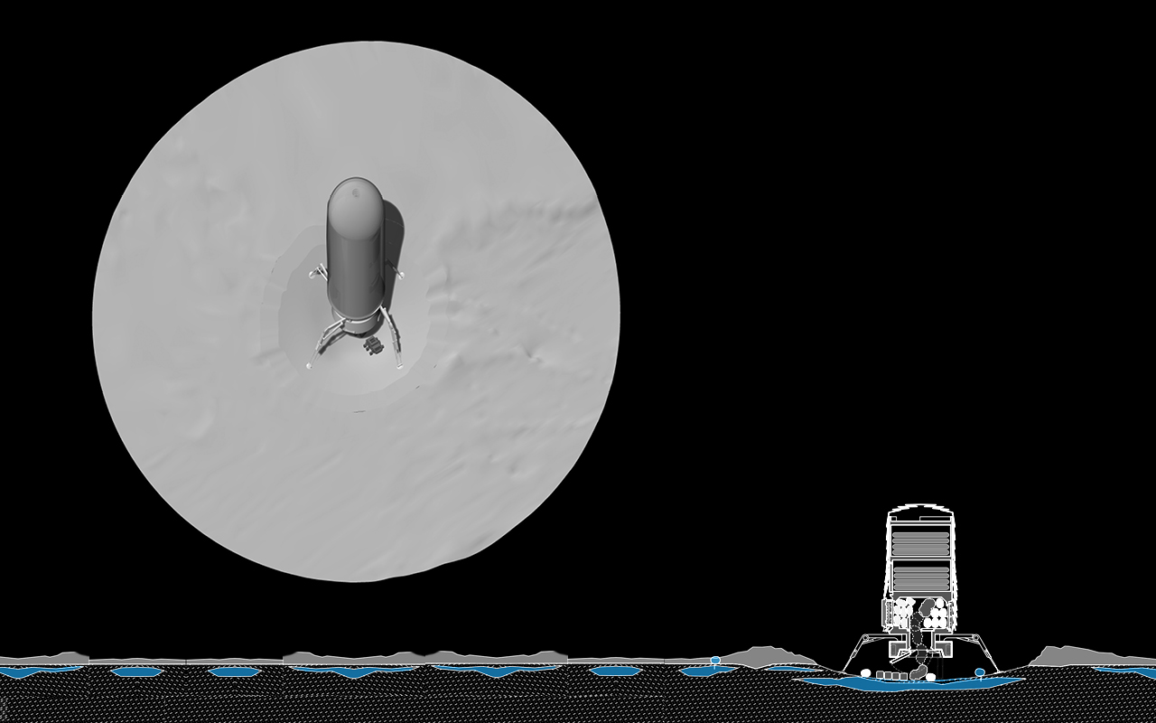
1. Descent
Deployment is initiated by a lander, sized for the currently available payload of a Space X Falcon Heavy and NASA’s Space Launch System (SLS), both of which are undergoing testing and development.
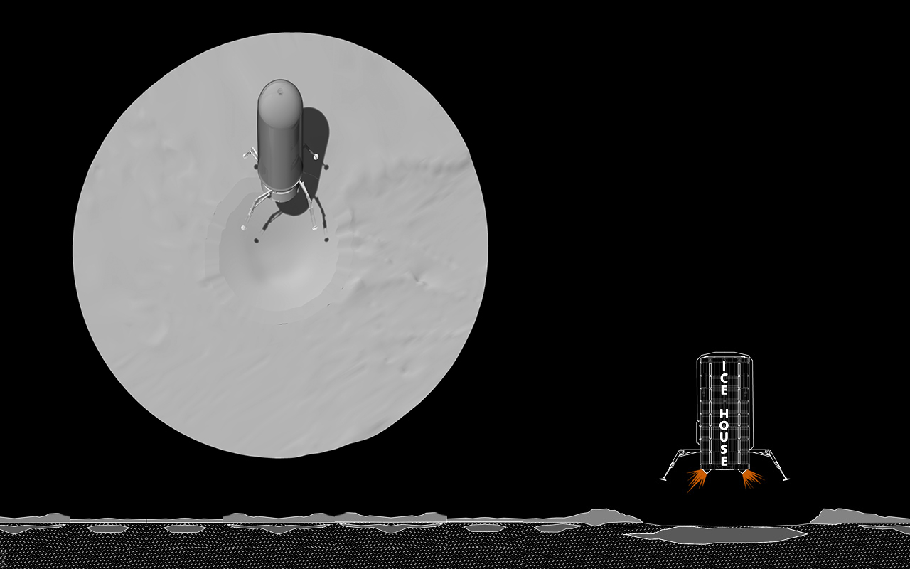
2. Landing
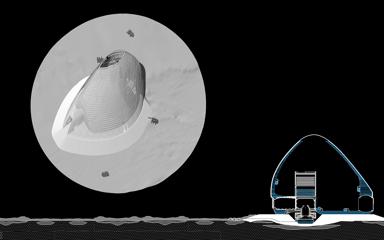
Once within the 3-sigma landing range, a 4x12 mile ellipse, retro-propulsion will blow off the thin upper layer of loose regolith, exposing the subsurface ice and causing it to sublimate, thereby leaving a crater in its wake and eliminating the need for excavation prior to printing a structural foundation.
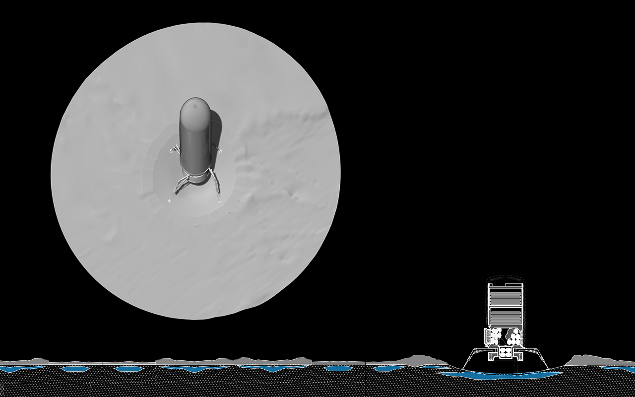
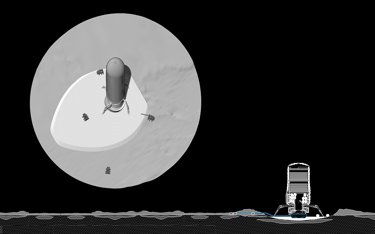
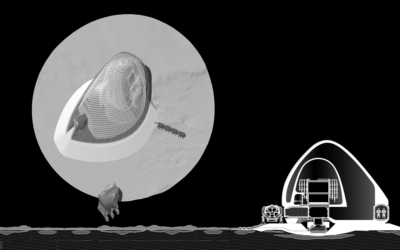
3. WaSiBo drop
The first phase of printing is exterior in focus, mining the surrounding landscape for water and creating a foundation in which to ground the lander. Bots engineered specifically for both sintering and ice harvesting drop from the lander’s base hatch, deployed to mine subsurface ice and build a new foundation.

4. Resevoir & Hose Deploy
Once released through the hatch, the WaSiBo s remain exterior, thereby avoiding potential contamination with the interior. The double acting machine uses it’s ability to shovel and heat regolith both to collect Martian dust and extract water and other volatiles, while its laser serves to both sinter waste regolith as well as cut solid ice below the ice table. All ice is melted and deposited within a reservoir bag for use in future printing as well as greenhouse maintenance. These bots are energy efficient and low maintenance, as they rely on the physics of sublimation rather than laborious geologic mining, using solar energy and the naturally cold environment (-50C) for the water, ice and vapor phase changes.
READ MORE about using the physics of phase change to collect water.
5. Sinter Foundation
The double acting WaSiBo collects and laser sinters regolith to provide a foundation for the ice habitat.
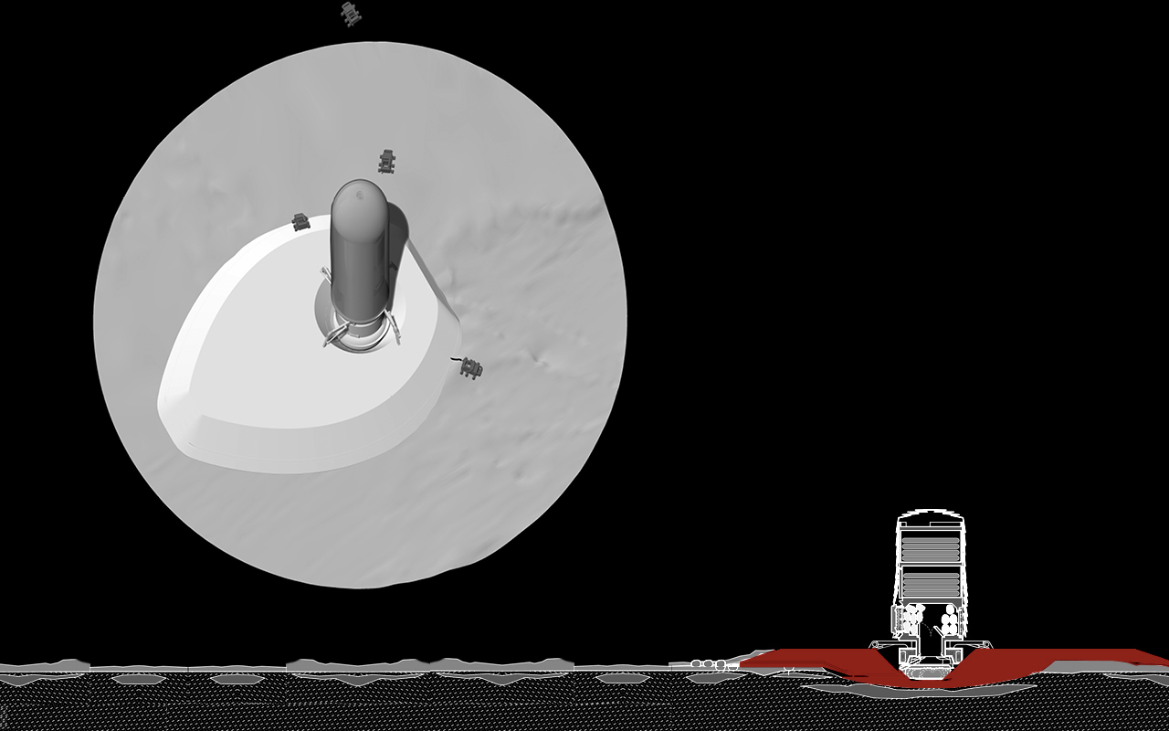
6. Sinter Foundation
The double acting WaSiBo collects and laser sinters regolith to provide a foundation for the ice habitat
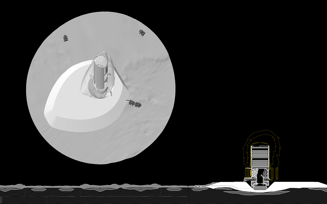
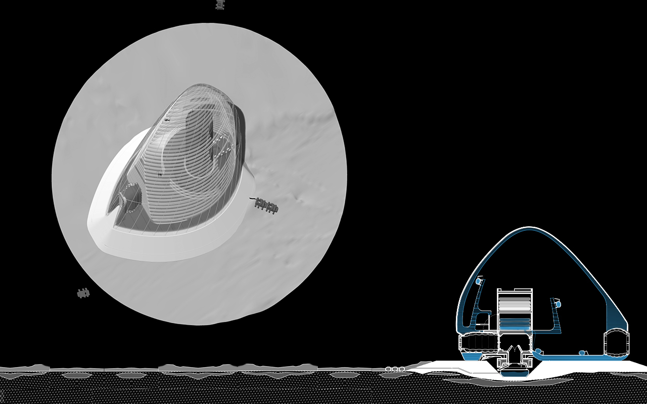
7. Inflate ETFE Membrane
A transparent and fully closed ETFE membrane reinforced with tensile Dyneema is deployed from the lander and inflated to form a pressurized boundary between the lander and the Martian exterior. This membrane, precision manufactured on Earth, is critical protection for the future ice shell, preventing any printed ice from sublimating into the atmosphere.
READ MORE about our inflated Dyneema reinforced ETFE membrane and it's stress performance.
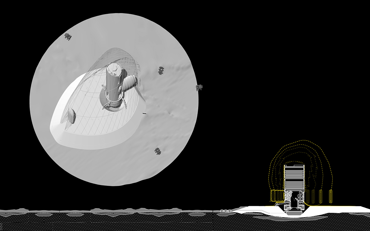
8. Inflate ETFE membrane
A transparent and fully closed ETFE membrane reinforced with tensile Dyneema is deployed from the lander and inflated to form a pressurized boundary between the lander and the Martian exterior. This membrane, precision manufactured on Earth, is critical protection for the future ice shell, preventing any printed ice from sublimating into the atmosphere.
READ MORE about our inflated Dyneema reinforced ETFE membrane and it's stress performance.
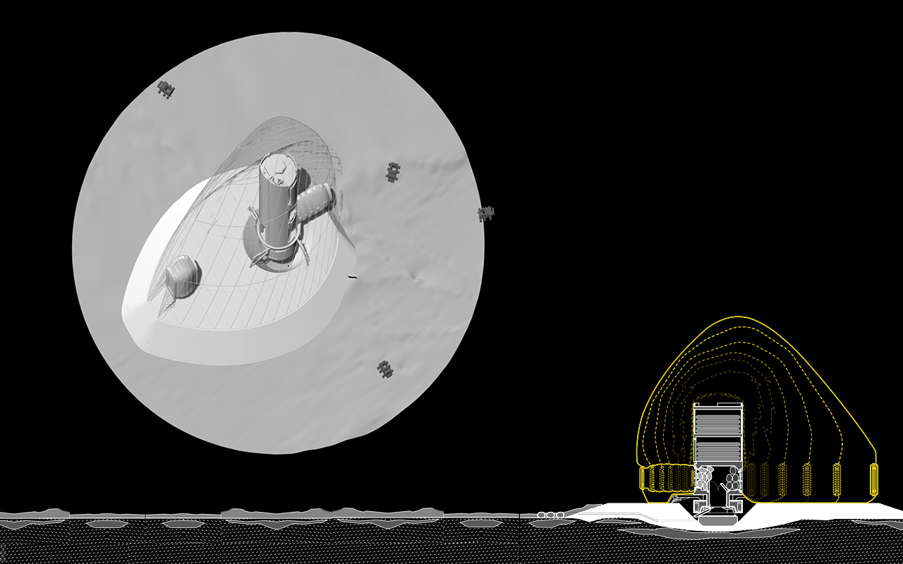
9. Deploy Airlocks
Inflatable/expandable airlocks are factory made and embedded within the ETFE membrane. Because this piece of hardware and it's connection to the overall pressure envelope is so critical, these components are made secure on Earth.
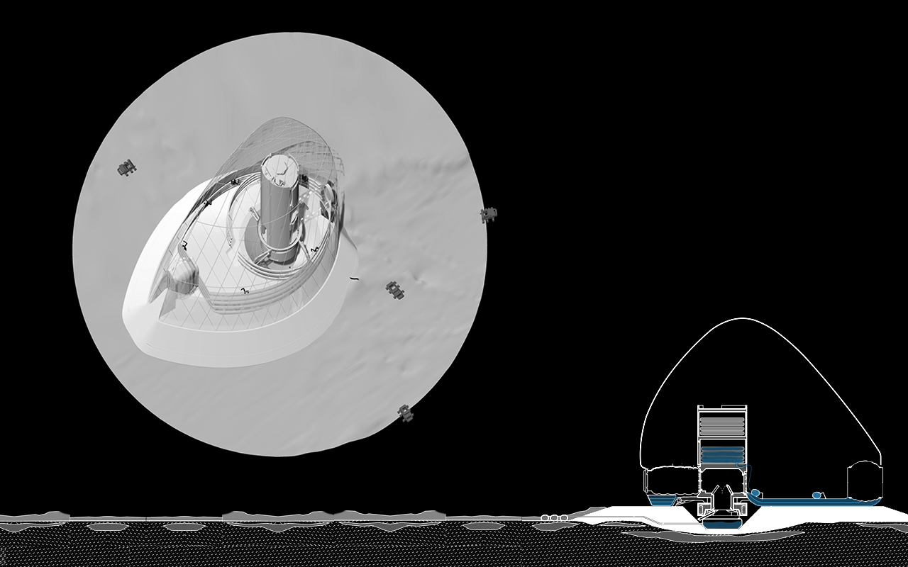
10. Print Ice
Following deployment of the ETFE membrane, ice bots are released from the lander into the pressurized pocket to commence the second phase of printing. These bots use a triple nozzle to dispense a composite of water, fiber and aerogel along layered rings, printing a spectacular light emitting lenticular form that is structurally sound, insulated and translucent.
READ MORE about 3D printing with ice.
11. Print Ice
The low-volume, close-range nozzle ensures that any water that freezes mid trajectory melts and refreeze instantaneously via the energy of its impact (a contact weld).
READ MORE about 3D printing with ice.
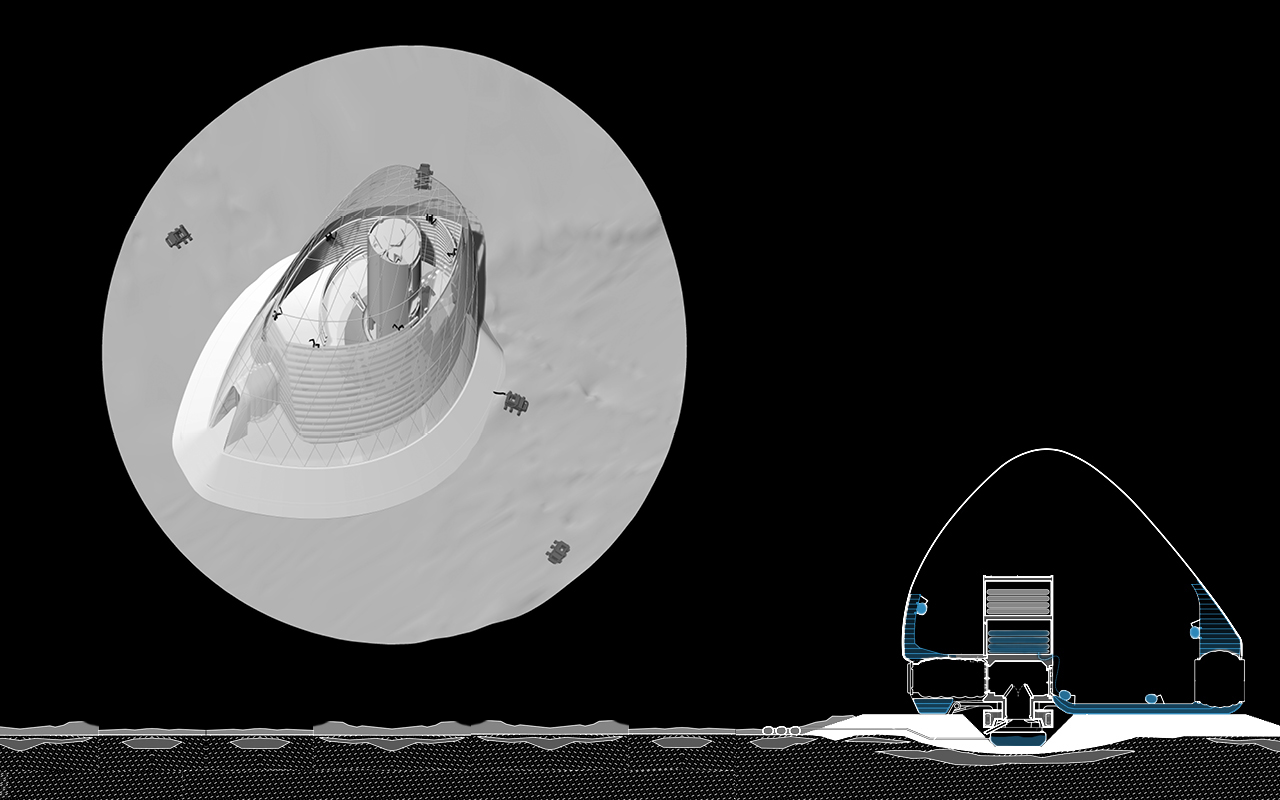
12. Print Ice
A fibrous clear silica additive (flat-packed in the lander) provides the ice form with greater tensile strength,9 calculated to bolster the strength of ice to the order of 3 times. While ice has been shown to possess tensile properties (~2-3 MPa)10 that are, in fact, superior to materials such as brick (2.8 MPa) and granite (4.8 MPa), the fibrous reinforcement ensures the longevity and integrity of the structure.
READ MORE about 3D printing with ice.
13. Print Inner Shell
A translucent hydrophobic aerogel layer with U values of 1 W.m2K and light transmittance of 66% is printed between the inner ice shell and the inhabited programmatic spaces to ensure thermal comfort.
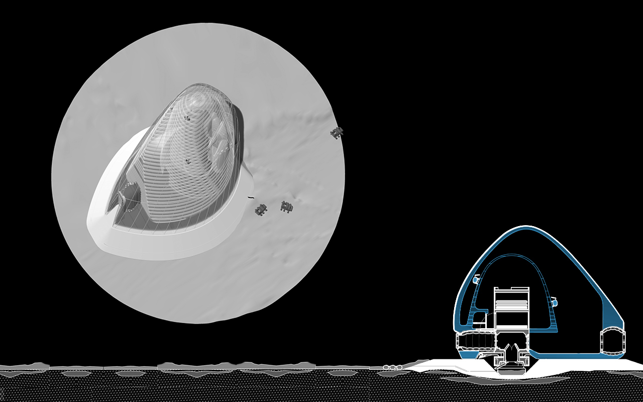
14. Print Inner Shell
A porous substance, 99.8 percent empty space by volume, this additional lightweight material brought on the lander from Earth, serves an efficient air gap to create the necessary thermal break. The insulating layer enables the inner volume to achieve habitable temperatures without melting the ice structure beyond.
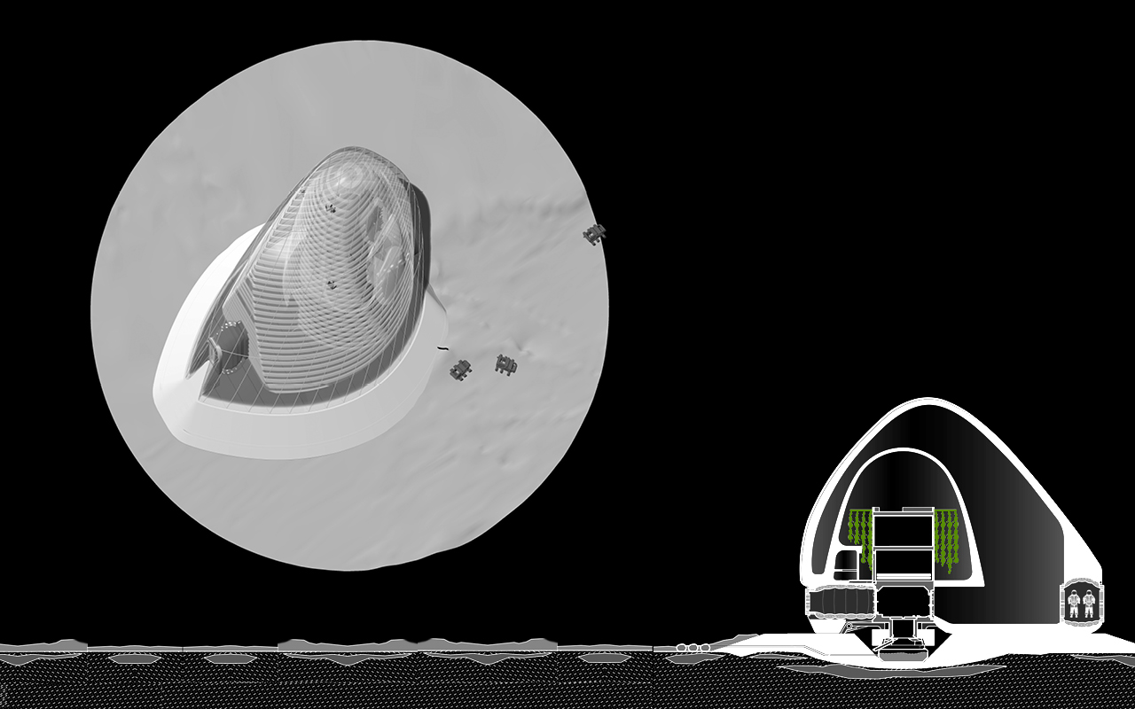
15. Grow Plants
Planters and seeds that have arrived with the lander begin to grow within the habitat. This hydroponic system grows using the subsurface water harvested by the WaSiBo s and stored in the foundation reservoir. Along with the mechanical ECLSS systems, these plants will help convert the CO2 of the Martian atmosphere (95% by volume) into the O2 needed to maintain human life.
The intermediate zone between the two ice shells will serve to maintain the optimal balance between 02 production and ideal air composition for the interior habitat. This will also assure that the Martian atmosphere will remain uncontaminated by human use.
READ MORE about the atmospheric composition of ICE HOUSE.
16. Crew Arrives
The vertically oriented lander, which contains the mechanical services of the habitat, inherits the likely orientation of the crew’s (MTV) Transit Habitat to ease the crew’s adjustment to life on the Martian surface.
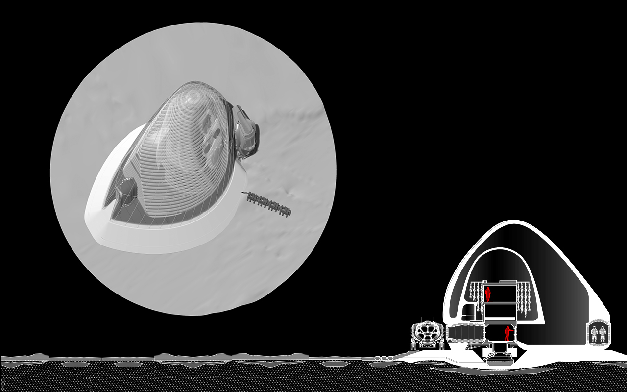
17. Crew Inhabits
The heat from the lander and the crew remains inside the habitat due to the layer of printed aerogel insulation.
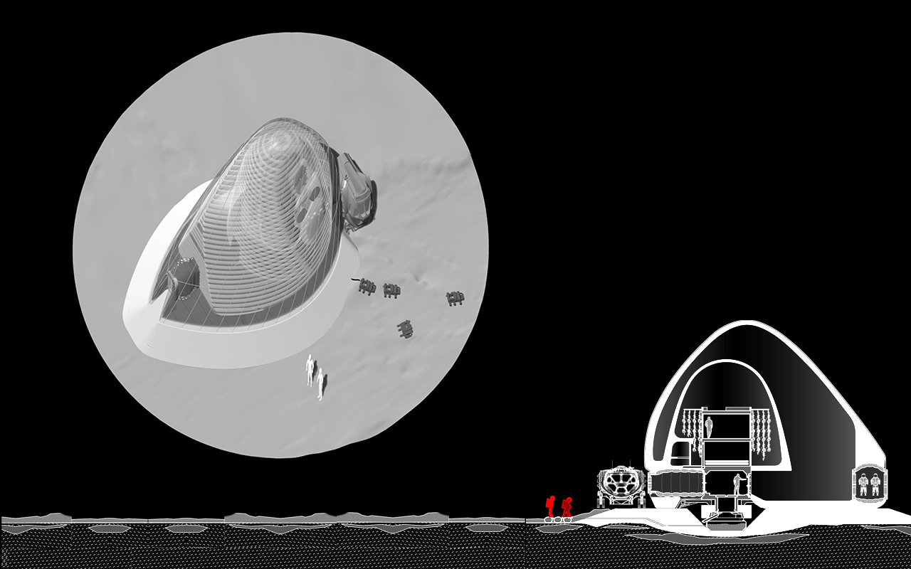
18. Crew Explores
With all EVA suits external to airlocks, we hope to keep out as much potentially toxic Mars regolith as possible.
Building on Mars